Best Of
Setting up PicoBricks for Use with MicroBlocks
FOR WINDOWS COMPUTERS:
Let's review the two way you can connect a PICO to the computer:
- BOOTSEL button pressed and then plugged into the USB port (used for firmware updates).
- Plugged into the USB without pressing the BOOTSEL button (for normal programming mode).
BOOTSELECT MODE:
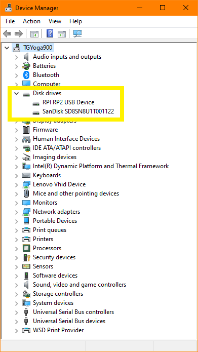
When you connect using option #1, your board will show up in the Windows Device Mgr as a disk drive, named: RPI RP2 USB Device
This is the method you should use to do a PICO firmware update from MicroBlocks.
Important point to remember - you need to:
- UNPLUG the PICO from the USB port
- Press and hold the BOOTSEL button
- And while holding it down, plug it into the USB port.
- At the moment you plug it in, you should hear a system sound indicating the USB port activation and subsequently the PICO should appear as a drive in your Windows system.
- Now you can let go of the button and proceed to firmware update.
- Please note that while in the firmware update mode, your MicroBlocks program will not be operational due to the fact that the IDE and the Pico board are in a mode to exchange firmware data.
- After the firmware update is completed, it is important to redo the USB connection. If you really want to be sure, just unplug and replug your board to your PC.
Normal programming mode:
When you connect using option #2, your board will show up in the Windows Device Mgr as a COM port, named: USB serial Device (COMnn). nn will vary in each system.
This method is used when programming the PICO from the MicroBlocks IDE.
Users experiencing "Pico not being visible or working within the system" in either mode might be due to several things:
Pico is not visible as a drive when plugged as in #1 above, or as a COM port when plugged in as in #2 above could be a hardware issue, as it has to do with assignment of drive or port status from Windows. The PICO board might be bad, or Windows might be having a problem activating the board. Contact Robotistan to assist you in resolving the issue.
Referring to "not working after update" might be interpreted / caused by one of the following:
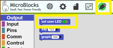
- If by "not working any more", you mean that when you first plugged PICO in, you were getting the environmental statistics display on the OLED screen; but after the update of MicroBlocks firmware, it did not display any more; this is normal. The initial display is done by a burned in Python program when the PICO was shipped. Once you do a firmware update, you overwrite this original program and there is no program running to display the stats. At this point, the PICO is ready to be programmed by you from scratch or via one of the examples in the Guide provided. A simple test you can do immediately is to get into MicroBlocks and click the USB icon and make sure you have a green USB connection icon.
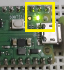
- Then select the "set user LED <true>" block. Click it and you should see the LED on the PICO light up.
- After a firmware update, you did not reinstate the USB port into a connected mode (green USB icon). Simply redo the USB connectivity.
- For some reason the firmware update was NOT successful. You can verify the update success by checking the firmware versions before and after:
If you cannot get the USB icon to go green, then you need to make sure the firmware on the PICO is up-to-date or installed at all (new boards will not have it installed). Go through the firmware update and try the USB connect icon again. If you get it to go green, then you should be able to program it.
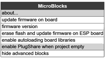
If you have a green USB icon, then you can also get a display of the IDE and firmware versions by selecting about from the wheel icon menu. You should see something like:
Report these numbers when you are asking for assistance to enable us to help you better.
I hope this sequence of trouble-shooting will help you identify if the problem is a bad hardware or a problematic firmware update.
Re: Setting up PicoBricks for Use with MicroBlocks
The above works for Windows computers.
With Linux (Mint), if you use the Bootsel option, you will see your Raspberry Pi Pico in your file manager.
and/or you will get an icon on your desktop.
When the firmware is updated the icon disappears just like the device that was previous visible.
Re: HC05 Not Working
What model of Bluetooth module do you have? Maybe on the packaging there is a notation.
My writeup is specific to HC-05, HC-06.
The fact that you are getting an OK means you somehow entered the Config mode, but light indicators are not as expected. This could be due to a different model of BT module.
Important thing is to verify good operation of the BT module. This will be hard to do from within the project code.
Much better option is to connect the BT module using a USB2Serial converter, which might not be readily available, and a terminal program on the Win PC.
There is another indirect way to test the connection.
Power up your setup normally with BT module in.
Go to your Android cell phone and open up BT options and see if your BT module is listed there.
If it is, at least it is operational and you can PAIR to it.
If no BT module is shown, you might have a defective unit.
If you do see your module, PAIR to it and try the project at 9600 baud setting.
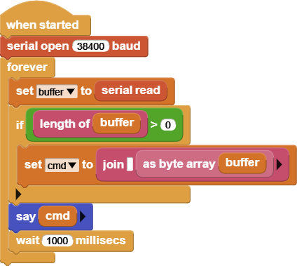
If you leave my modified code with the "say cmd" block within the loop and a 1sec wait, you should see any messages coming in from the mobile voice control APP.
If you see garbled input, baud rate is wrong in the BT module.
Yes, this was a very long-winded post, but comms troubleshooting over forum postings is not an easy thing to do.
I can try to assist over a video conference link, if your schedules permit.
You can contact me over my email, to free up this space. My timezone is GMT+3.
Some Helpful Tips / Links for MicroBlocks Users
When you are working in the IDE, as you move the mouse over the various blocks in the menus, the bottom status line will display a short description of the block your mouse is over.
Upon right-clicking any block, one can also select help and be transported to the User Guide and Block Reference pages of the MicroBlocks WIKI for a more detailed description and use examples for the block selected.
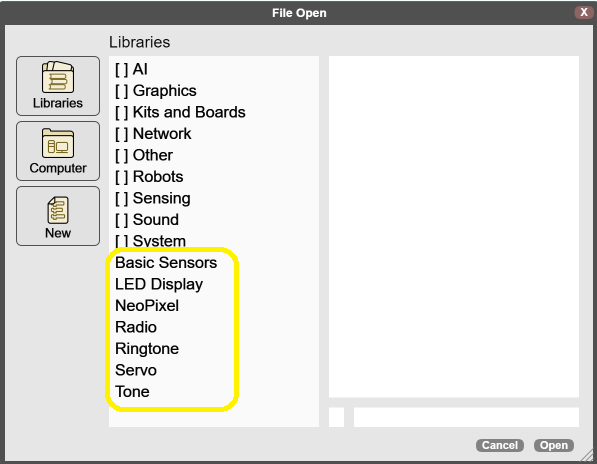
Right-click / help option also works for the main set of libraries displayed when the Libraries menu is opened, as well as for the OLED Graphics, PicoBricks, Maqueen, and HuskyLens libraries.
As you are editing in the IDE, you can right-click and use the clipboard as a copy / paste environment to move / copy blocks of code or individual blocks.
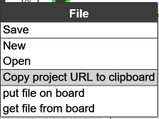
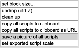
When you finalize your creation and want to share it with your friends, simply use one of the options below:
Will place an URL link to the clipboard that you can share or post onto web sites. This and the normal File/Save options creates a complete copy of the program.
When the URL is clicked, a MicroBlocks browser window will open up with your project loaded.
A picture of the visible parts of your program in the IDE will be generated as a PNG image file. It will contain the code of your program (global variables and user-defined functions that are not actually used by the scripts are not included) embedded as an extended header option. You can send this image file to anyone. Due to the fact that global variables and user-defined functions are not included in this version, it is not to be relied upon as a recovery file for the original program source.
When this image is dragged/dropped onto the MicroBlocks IDE, it will load your program ready to run.
When your program is in good running order, it is stored on the board connected to your PC with an USB cable. Please note that this stored version is somehow abbreviated and does not contain comments and script positions saved on the board. When you disconnect the cable, your code stays on the board.
Now, enable the plugshare option shown in the menu, and select NEW from the File menu to clear the IDE. When you plug in the board, your program will be loaded and ready to run. Due to the fact that script positions and comments are not included in this version, it is not to be relied upon as a recovery file for the original program source.
But the best part is, you can give your microcontroller to someone else, or take it to another PC and plug it in. And with the IDE settings as above, you can start running your program on the new PC.
Our WIKI is full of very useful information on programming with MicroBlocks, as well as the variety of micro controller boards supported. One of the unique features is that your program is totally transferable to any of the supported boards, provided the feature sets are compatible. Even if your program uses blocks that are using a features not supported on the new board, MicroBlocks will simply ignore those blocks and your program will work without a problem.
Enjoy the physical computing and real-time programming with PicoBricks and MicroBlocks .
Re: HC05 Not Working
HC-05 Users,
You cannot use the module blindly. Need to know what state it is in and its default settings.
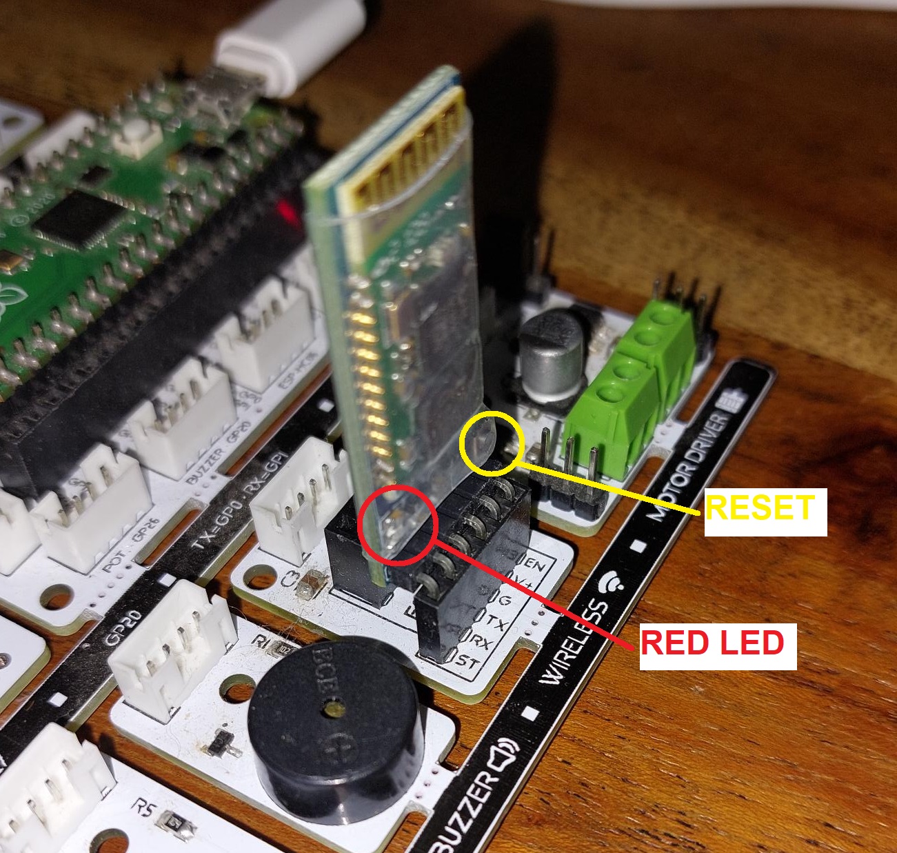
Normally, the module will have a RESET button on it to put it into CONFIG mode.
Pressing the button, insert it into the BT slot on picobricks as shown in the picture below.
You either have a 6-pin module or a 4-pin module.
6-pin module inserts one pin into each slot.
4-pin module needs to be inserted into the CENTER four pins, leaving the two edge pins unused.
You should have a Red LED blinking at 2sec intervals. That indicates you are in the CONFIG mode. Config mode operates at 38400 baud.
Now we need to check out the settings of the HC05 :
Load the MicroBlocks program for the Voice Controlled Robot Car.
Modify the WHEN STARTED script to look like below, or drag and drop the script picture onto the IDE:
Now we need to add the following block from the COMM group onto the IDE:
If you don't see the COMM group, enable "show advanced blocks" from Settings (the wheel).
We are going to enter AT commands into the first text area of the block and click on it to transmit.
Responses will be shown in the running WHEN STARTED block.
Click on the When started block to execute it. It is in a loop, waiting for responses from the HC05.
Type "AT" into the text area (without the quotes) and click on the block. You should get an OK from the unit.
If this does not work, your setup is not right, or your HC05 is not inserted right, or defective.
If you have gotten an OK to the first transmission, let's continue:
Type in "AT+NAME=HC-05" and click on the block. This sets the unit name to HC-05.
You should see OK as a response.
Now we check the operation mode: Type in "AT+ROLE?" and click on the block.
You should see +ROLE:0 OK, meaning the unit is in SLAVE mode.
Now we check the unit password: Type in "AT+PSWD?" and receive hopefully 1234.
This is the default.
If you get something else, change it to 1234 with AT+PSWD="1234". You need quotes around the pswd.
Now you should get an OK.
Then verify the password with "AT+PSWD?" and get back what you entered.
Then we need to check the interface speed: Transmit "AT+UART?"
You should get: +UART:115200,0,0 OK.
You might get different speeds shown. Whatever you get, we need to change it to 9600 to work with the mobile APP.
Send "AT+UART=9600,0,0" and receive OK.
Afterwards you can verify again by redoing the previous AT+UART? command.
It should show +UART:9600,0,0.
If you have successfully done all that, you should be ready to communicate with it from the APP.
Power cycle your board,
Your HC-05 unit RED LED will be flashing rapidly, indicating it is operating normal.
When you link to it from the APP, the RED LED will be flashing two times every five secs. This is the normal communication mode.
Your unit name is HC-05 and should show up in the Android BT list.
Pair to it and use password 1234 when asked.
Reload the original Voice Controlled Robot Car script into the MicroBlocks IDE.
Run the Mobile APP.
Hope this is helpful for you to get started.
Re: HC05 Not Working
I don't know that answer, I've never used one either. Hoping someone who has can also weigh in. Will try again tomorrow with my phone closer and follow up here.
Re: Individual trays
You have my permission to share the link to my printable page on GitHub.
